Topic: DMD0402

AXGEAR- Axis Electronic Gearing
Note: this instruction can only be used with a BRX CPU !
The Axis Electronic Gearing (AXGEAR) instruction is used to create a Master / Slave connection that will synchronized the movement of one Axis to another Axis or a High-Speed Counter / Timer.
Note: the Master and Slave Axes must be on the same hardware. This means if the Master Axis is using the on-board discrete I/O then the Slave must be one of the Axes or High-Speed Counter / Timers also using on-board discrete I/O; if the Master Axis is on one of the BRX HSIO modules (BX-HSIO1, BX-HSIO2, or BX-HSIO4) then the Slave must be one of the Axes on the same HSIO module.
Note: only the BX-HSIO4 module can operate at velocities above 250KHz; attempting to use a velocity above 250KHz for an Axis that is using the on-board High-Speed I/O, or an Axis on a BX-HSIO1 or BX-HSIO2 module will result in a maximum velocity of that Axis still being 250KHz.
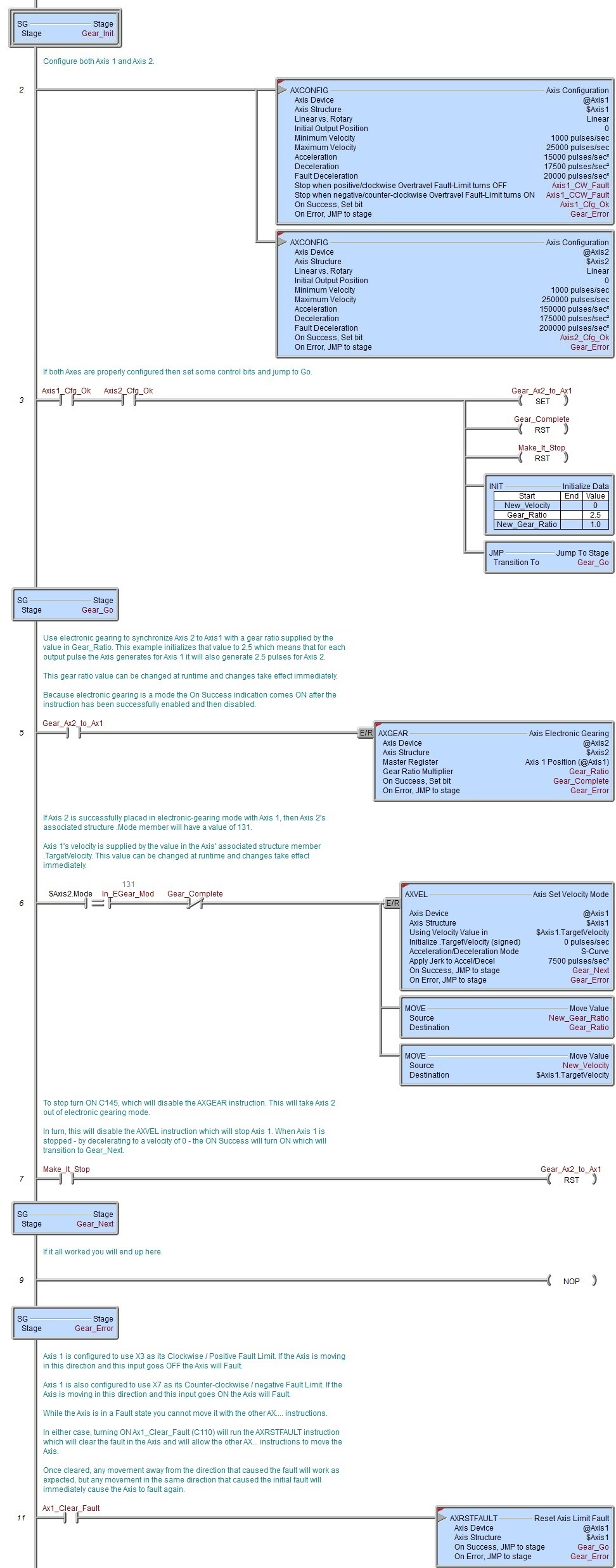
If the Axes will be used in a velocity-centric application where the velocity and gear ratio will be manipulated, the Slave's velocity is derived from the Master's velocity so that any change to the Master's velocity will result in a change to the Slave's velocity which has been adjusted by the user-supplied gear ratio. Both the Gear Ratio and the Master's Target Velocity can be changed while the Axes are moving and the changes take effect immediately.
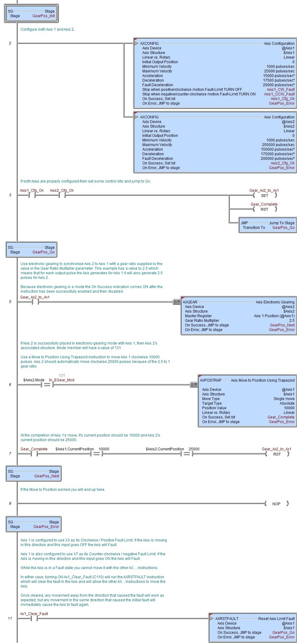
If the Axes will be used in a position-centric application where the position and the gear ratio will be manipulated, the Slave's position is derived from the Master position so that any time the position of the Master Axis changes the position of Slave Axis will move to a position that has been modified by the user-supplied gear ratio. When the move to position operation is enabled, the instruction will use the current values of the Gear Ratio and the Master's Target Position to calculate the move profile. Any changes to the Gear Ratio and Target Position while the Axes moving will be ignored.
To help keep track of the Axes movement relative to each other, any time the Axis is in Electronic Gearing mode the Slave Axis' associated structure member MstSlvCoordError will contain the difference (in pulse counts) between the Master Axis' position and the Slave Axis' position.

Axis Device selects which Axis to use as the Slave Axis - remember that Axis 0 is a virtual Axis meaning it will not generate pulses to physical outputs on the PLC.
Axis Structure displays the name of structure associated with this Axis. This structure was automatically created when the Axis itself was created.
Click the gear symbol at the right end of the Axis Device name to open the BRX Axis / Pulse Outputs configuration dialog where the Axis' Pulse Output Mode is set and its High-Speed I/O outputs are selected.
Master Register selects the Axis or High-Speed Counter / Timer that the Slave Axis will be electronically geared to. Note: this must be one of the Axes or High-Speed Counter / Timers on the same hardware as the Axis Device, this means if the Axis is using the on-board discrete I/O then the Master Register must be one of the Axes or High-Speed Counter / Timers also using on-board discrete I/O; if the Axis is using the discrete I/O on one of the BRX HSIO modules (BX-HSIO1, BX-HSIO2, or BX-HSIO4) then the Master Register must be one of the Axes or High-Speed Counter / Timers using discrete I/O from the same HSIO module.
The Non-Axis Master Filter Time is only enabled if the Master Register is a High-Speed Counter / Timer. This value is the Filter Time Constant which specifies how often (in seconds) the Slave's position is calculated. This can be any constant value or any numeric location.
Gear Ratio Multiplier is a multiplier that will be applied each time the Slave's position is calculated during a position move, or the Slave's velocity during a velocity move. A value of 0 will cause the Slave Axis to stop. Negative values will cause the direction of the Slave to be the reverse of the Master. This can be any positive or negative constant value or any numeric location. Note: to make it possible for the Master and Slave Axes to get synchronized - and remain synchronized if the Gear Ratio changes - the performance of the Slave axis must be significantly higher than the Master axis. Setting values for the maximum frequency, maximum acceleration, and maximum deceleration of the Slave axis to at least twice those of the Master axis is a good starting point.
This instruction puts the specified Axis into an operational mode - as opposed to performing a single operation. Because this is a mode change operation, ON Success is defined as getting the Axis into this mode and back out of this mode with no errors or faults.
When the input logic turns ON, the On Error indication will turn ON if there is a problem getting the Axis into the this operational mode. It will remain OFF if the mode change is successful.
Once the Axis is in this mode, the On Success indication will turn ON after the input logic turns OFF and the Axis' decelerates to 0 (the Current Velocity reaches 0). At this point the Axis' Mode will be "Idle". Once the input logic turns OFF and the deceleration phase begins, if the input logic turns back ON while the Axis is still decelerating, the Axis will NOT start moving again. You must wait until the On Success indication turns ON - the Axis must be "Idle" - before attempting to run any other Axis instruction.
The On Success and On Error parameters specify what action to perform when this instruction completes. You do not have to use the same type of selection for both On Success and On Error.
If the Set Bit selection is used for either On Success or On Error, the specified BIT location will be SET OFF when the instruction is first enabled and will remain OFF until the instruction completes. Once complete, the appropriate Success or Error bit location will be set ON. The specified Bit location is enabled with a SET (Latch) operation not an (OUT) operation meaning that it will remain ON even if this instruction's input logic goes OFF.
If the JMP to Stage selection is used for either On Success or On Error the target Stage must be in the same Program code-block as this instruction, you cannot specify a target Stage that exists in a different Program code-block. When the operation finishes, the target Stage will be enabled the same way as a standalone Jump to Stage (JMP) instruction would do it. The JMP to Stage option will only be selectable if this instruction is placed in a Program code-block.
On Success selects which of the following actions to perform if the operation is successful:
- Enable Set Bit then specify any writable bit location.
- Enable JMP to Stage then specify any Stage number from S0 to S127
in the current Program code-block.
On Error selects which of the following actions to perform if the operation is unsuccessful:
- Enable SET Bit then specify writable bit location.
- Enable JMP to Stage then specify any Stage number from S0 to S127
in the current Program code-block.
If either the On Success or On Error selections are set to JMP to Stage, Automatically create the SG box for any NEW stage number will be enabled which will automatically create any target stage that does not already exist.
- Below this rung will create the new target stage on a new rung following this instruction.
- At end of code-block will create the new target stage as the last rung of this Program.
Status Display
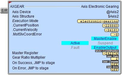
The red triangle in the upper left corner of the status display indicates this is a Fully Asynchronous instruction.
Execution Mode shows the current mode of the Axis (see a list of the possible execution mode values).
Execution Mode / CurrentPosition / CurrentVelocity / MstSlvCoordError are the current values of these numeric fields from Axis' associated structure.
MasterEnable / Active / Suspend / Fault / EnableOutput are the current state of these Bit values from that Axis' associated structure.
A detailed description of the Numeric and Bit fields is available in AXCONFIG - Axis Configuration.
See Also
AXSETPROP - Axis Set Properties
AXRSTFAULT - Reset Axis Limit Fault
AXSCRIPT - Run a Sequence of Axis Commands
AXHOME - Axis Perform Home Search
AXPOSTRAP - Axis Move to Position Using Trapezoid
AXPOSSCRV - Axis Move to Position Using S-Curve
AXVEL - Axis Set Velocity Mode
AXGEAR - Axis Electronic Gearing
AXFOLLOW - Axis Position Following with Offset
AXCAM - Axis Electronic Camming
Related Topics
Velocity-centric Example
Position-centric Example